Network Routing and Communication

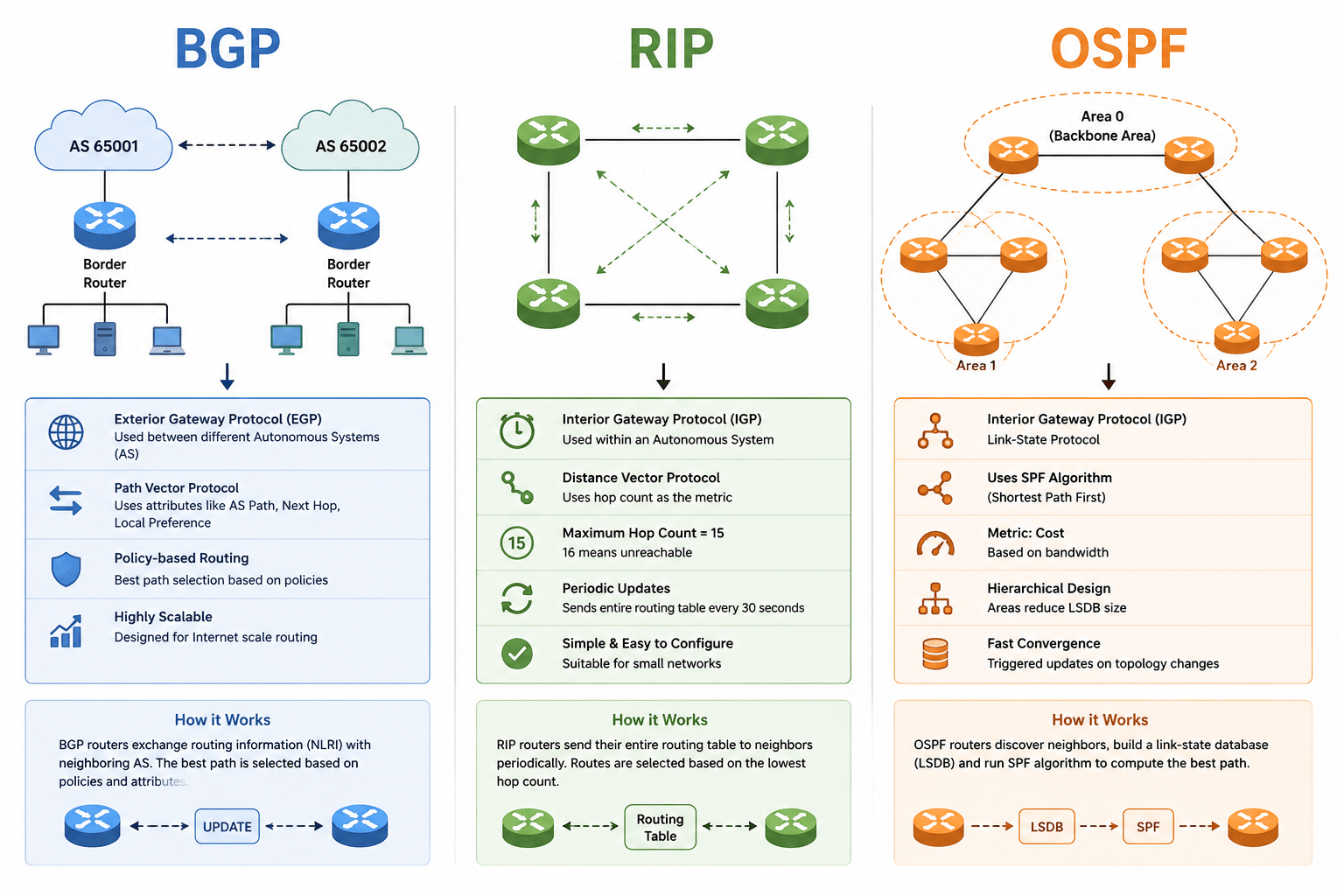
Routing Protocols – BGP, RIP, OSPF

Learning Outcome
5
Apply the concept to real-world networking scenarios
4
Describe how routing decisions change dynamically
3
Explain how routers choose the best path
2
Differentiate between types like RIP, OSPF, and BGP
1
Understand what a routing protocol is and why it is needed
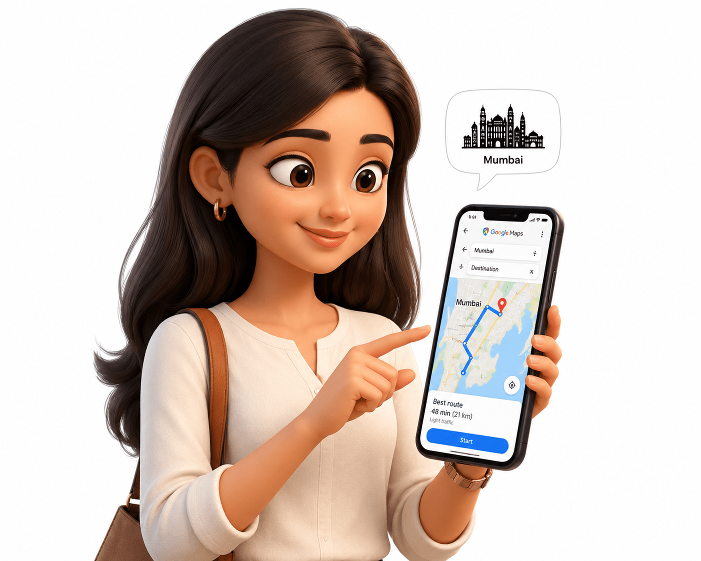
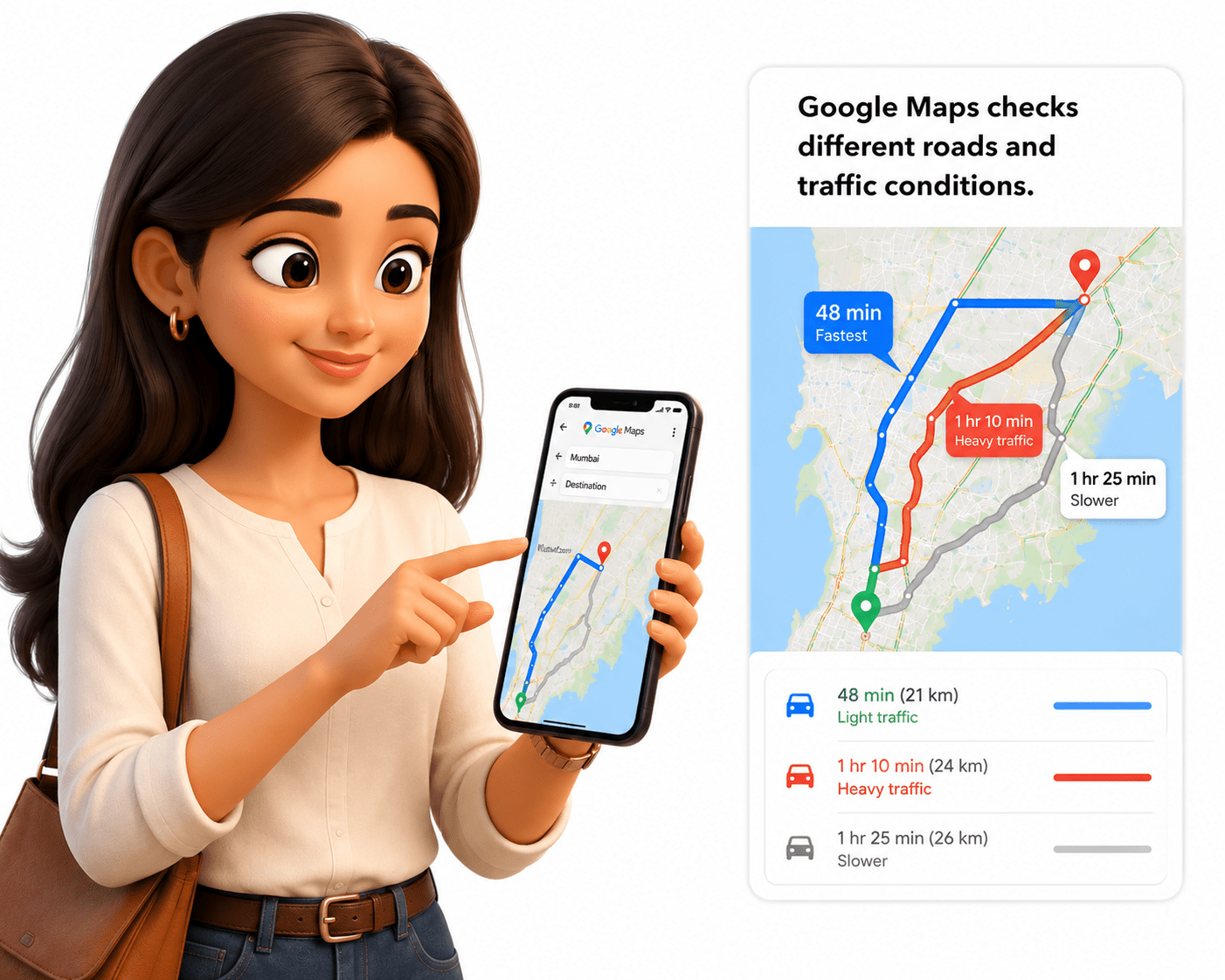



First, you write what you want to send.
Then the gift is packed safely and labeled correctly.
The delivery company manages the connection between you and your friend.
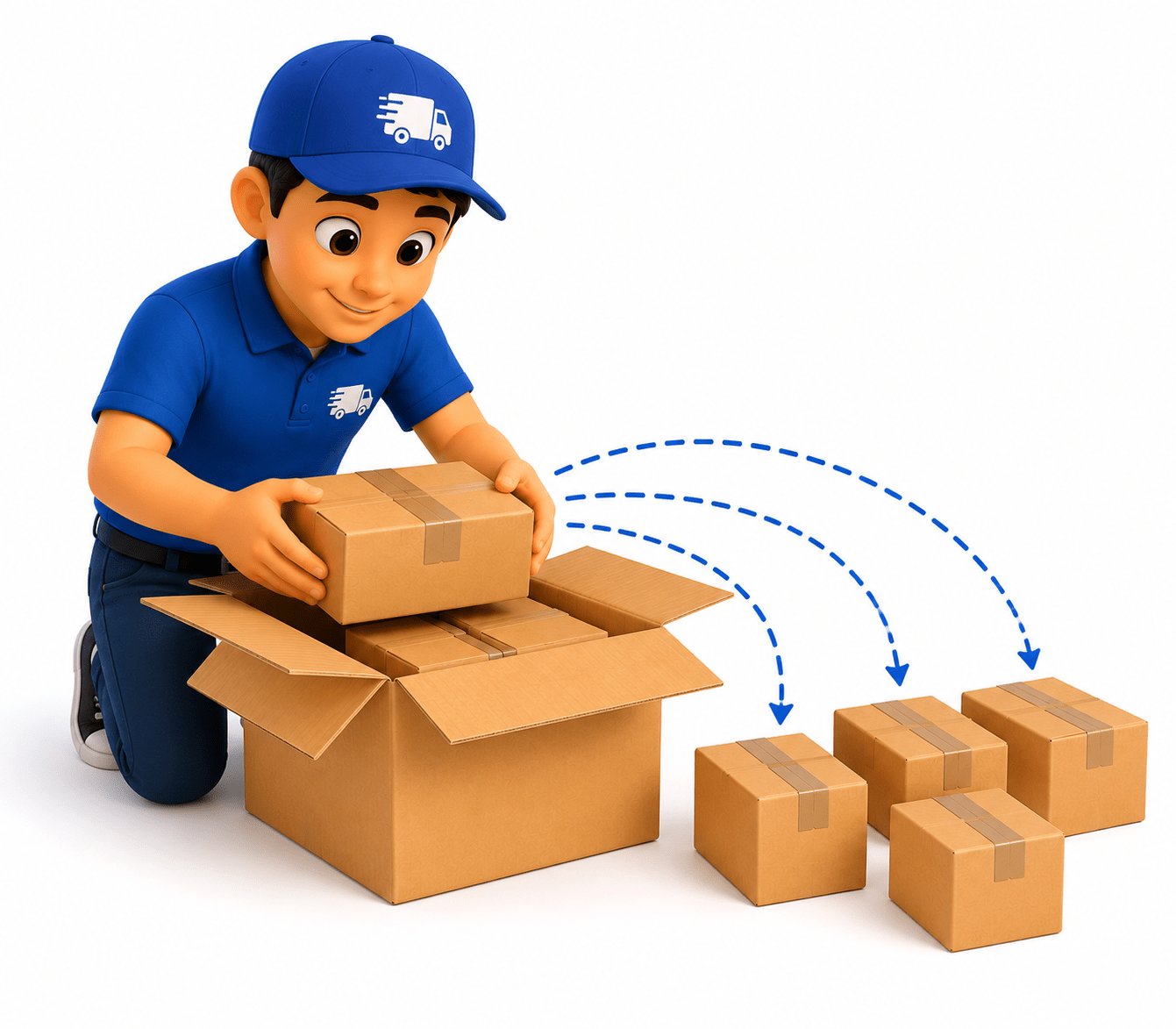
The package is divided into smaller boxes for easy transport.
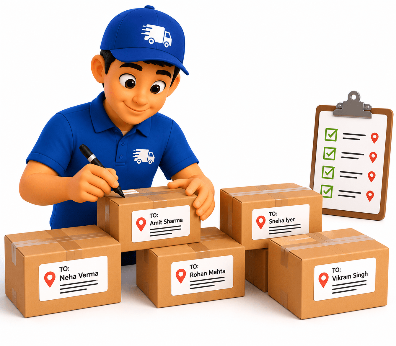
Each box gets an address so it reaches the right place.
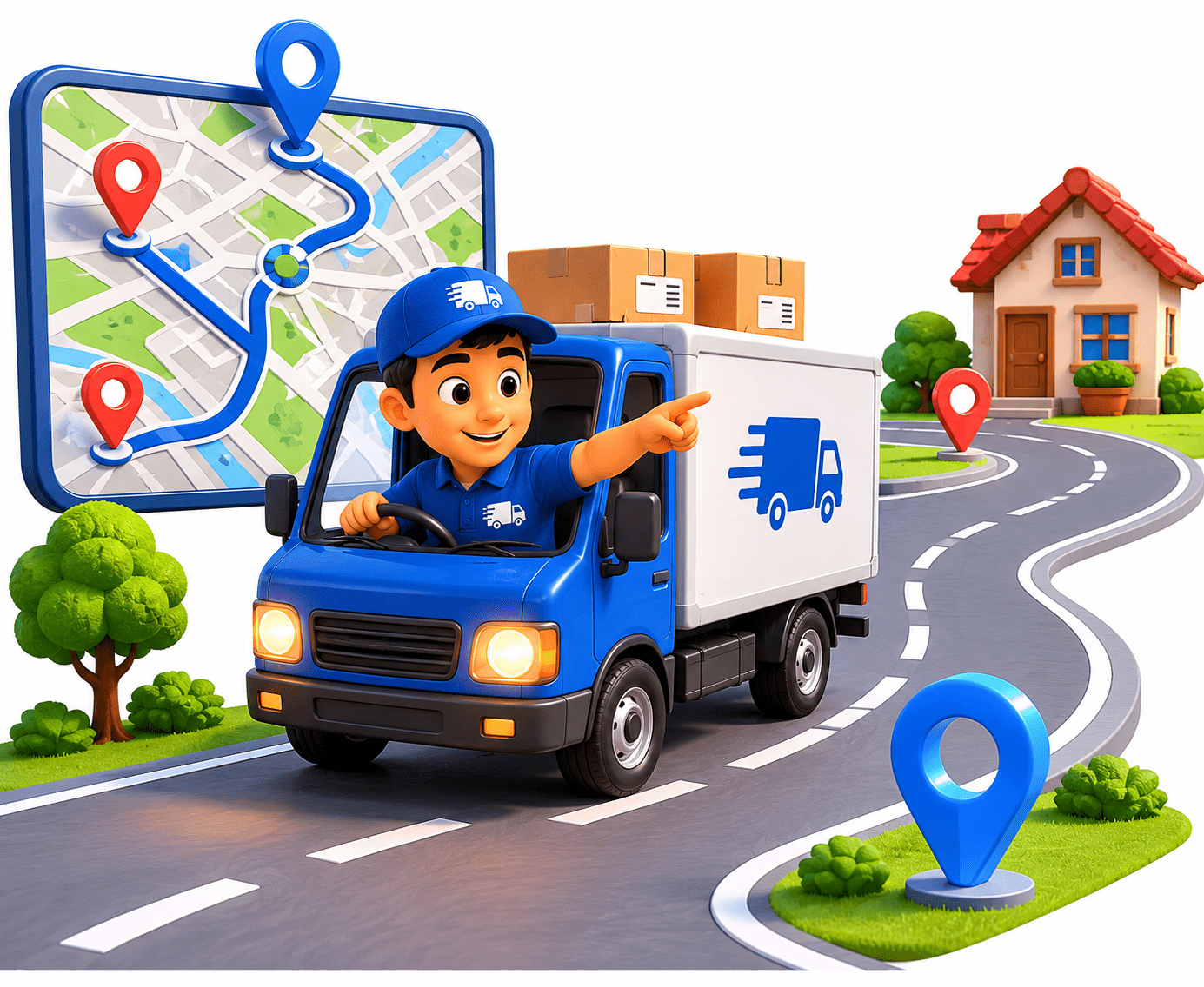
The delivery trucks find the best roads to travel.
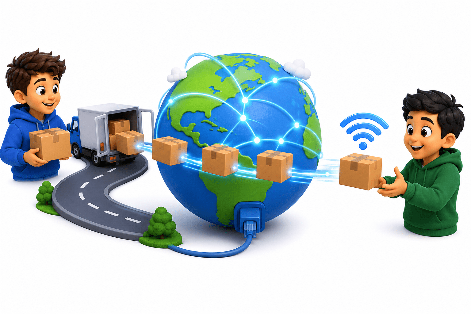
Finally, the boxes move through roads, cables, or Wi-Fi signals across the internet.
Helps understand how data moves between devices step by step
Breaks complex networking into smaller, easy-to-manage parts
Makes it easier to identify and fix network problems
Ensures different devices and systems can work together properly
Helps in designing and improving network communication systems
Provides a standard structure for learning and understanding networking
Use of OSI Model
Introduction to OSI Model
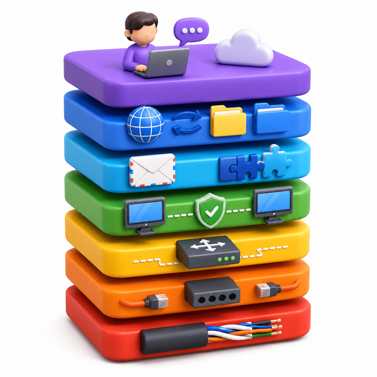
The Open Systems Interconnection (OSI) model is a conceptual 7-layer framework developed by the ISO in 1984 to standardize computer networking functions, enabling diverse systems to communicate. It divides data communication into layers (physical to application) for troubleshooting and understanding network protocols.
Purpose of Layered Architecture

Layered architecture divides networking into smaller parts to make it easy to design, understand, and troubleshoot.
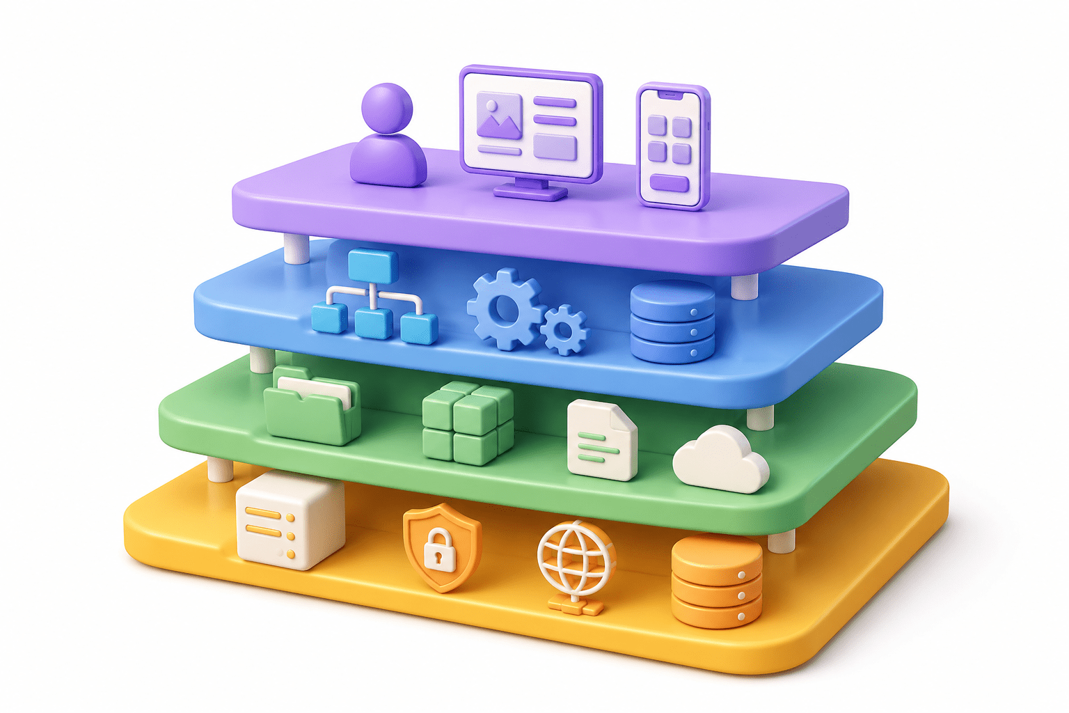
Why this is done?


Separation of work (Specific job for each layer)
-
Each layer handles only one function.
-
Example: One layer handles routing, another handles encryption.
-
This makes the system organized and efficient.
Easy to learn and understand
-
Breaking networking into layers helps students and engineers understand the process step-by-step instead of all at once.

Simplifies troubleshooting (Error detection)
-
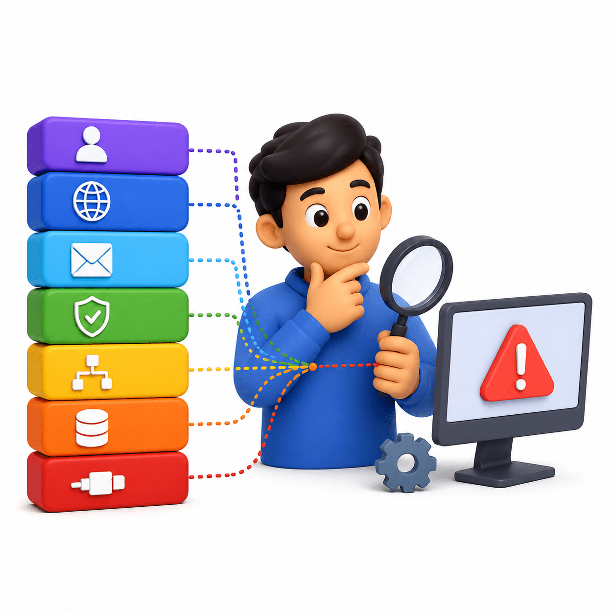
If something goes wrong, we can identify the exact layer causing the issue.
-
Example:
-
No signal → Physical Layer problem
-
Wrong IP → Network Layer issue
-
Flexibility and independence
-
Changes in one layer do not affect other layers.
-
Example: You can upgrade hardware (Physical layer) without changing software.
Interoperability (Different systems can work together)
-
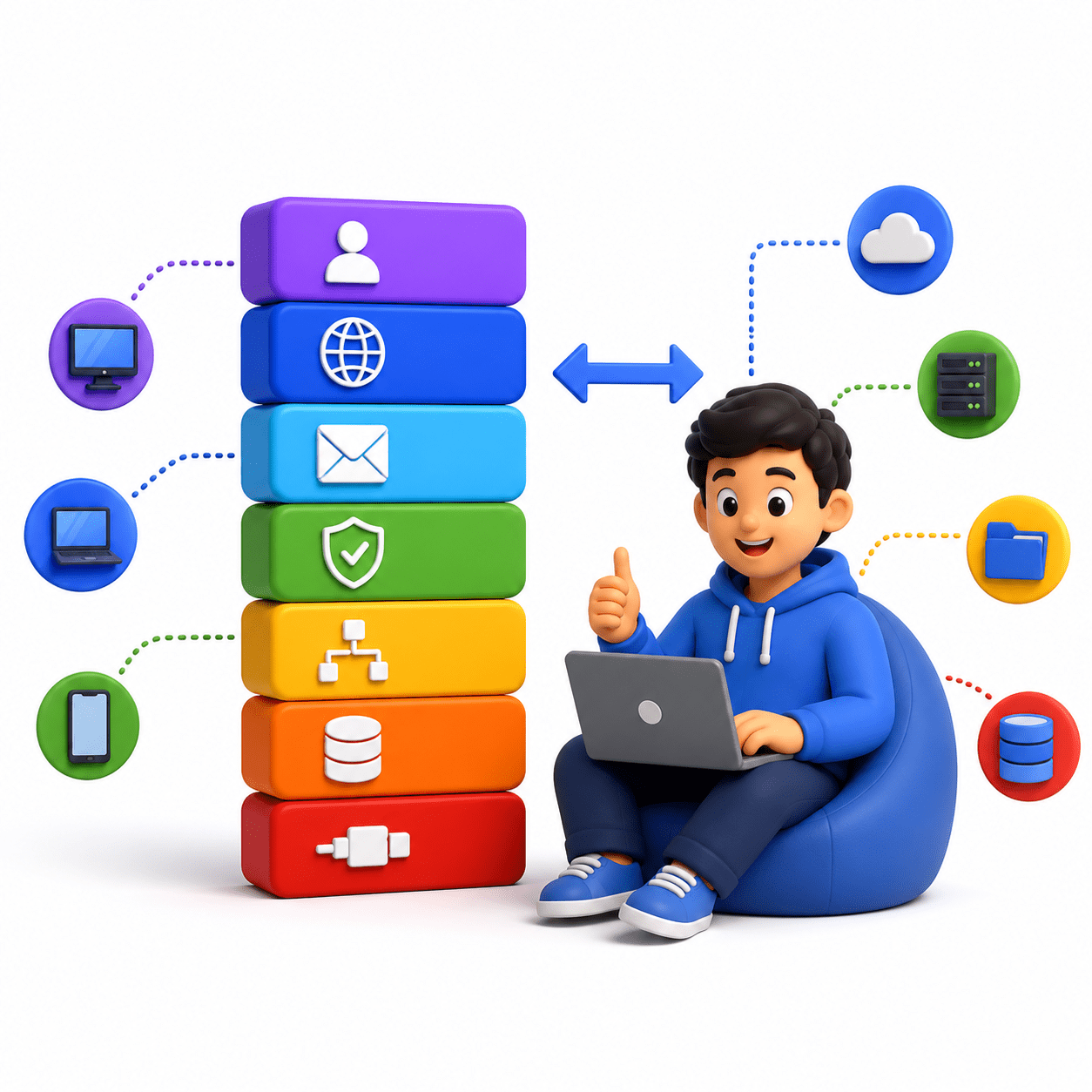
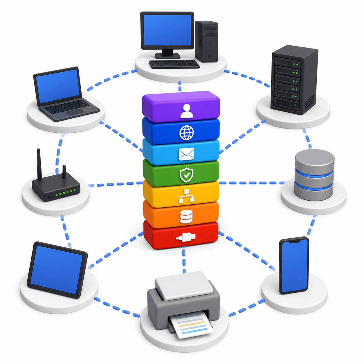
Devices from different companies can communicate because they follow the same layered structure.
Reusability of protocols
-
Same protocols (like TCP/IP) can be used in different applications without redesigning everything.

7 Layers Overview
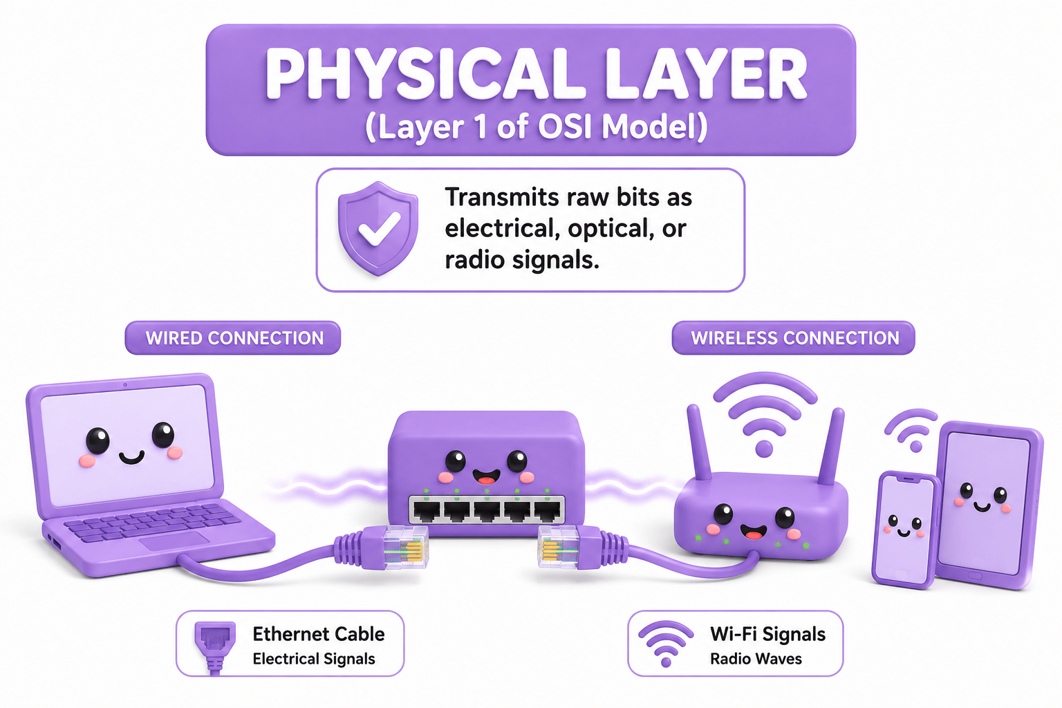
Transmits raw bitstreams over physical mediums (cables, switches). Responsible for the transmission and reception of raw bit streams over a physical medium, including electrical, optical, or radio signals.

Deals with cables, signals, hardware
Sends raw bits (0s and 1s)
Example: Ethernet cable, Wi-Fi signals
Physical Layer (Layer 1):
The Data Link Layer makes sure data moves correctly between devices on the same network using their physical (MAC) addresses. It checks for errors and ensures the data reaches the right device nearby.
Uses MAC address
Handles switching & error detection
Example: Ensures data reaches the correct device in the same network

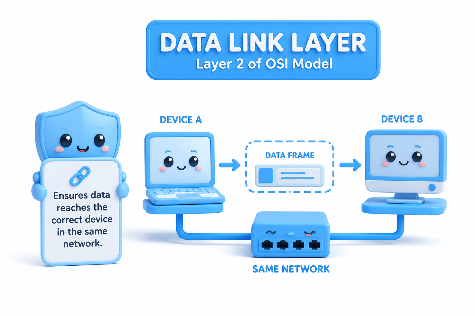
Data Link Layer (Layer 2):
Network Layer (Layer 3):
The Network Layer is responsible for sending data from one network to another using IP addresses. It decides the best path for data to reach its destination.
Uses MAC address
Handles switching & error detection
Example: Router deciding best path to send data

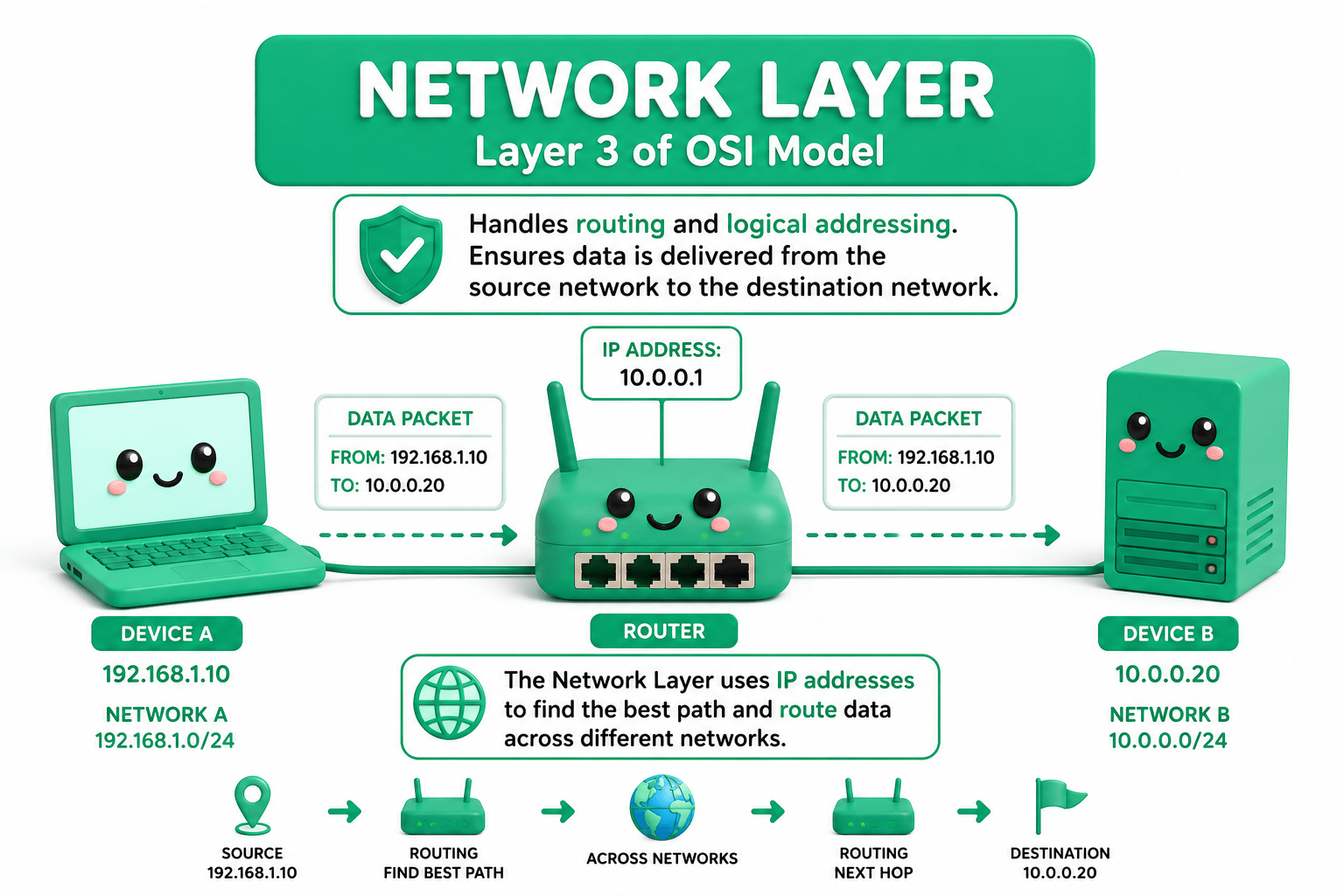
Network Layer (Layer 3):
Ensures reliable data transfer, flow control, and segmentation (TCP/UDP). Provides end-to-end communication services, including segmentation, flow control, error detection, and reliable or unreliable data delivery between hosts.
Uses TCP/UDP
Ensures data is delivered correctly
Example: Breaking data into parts and reassembling

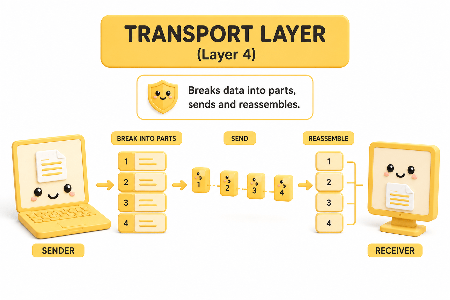
Transport Layer (Layer 4):
Manages sessions (connections) between applications. Establishes, manages, and terminates communication sessions between applications, including synchronization and dialog control.
Manages connection (start, maintain, end)
Example: Keeping a video call connected

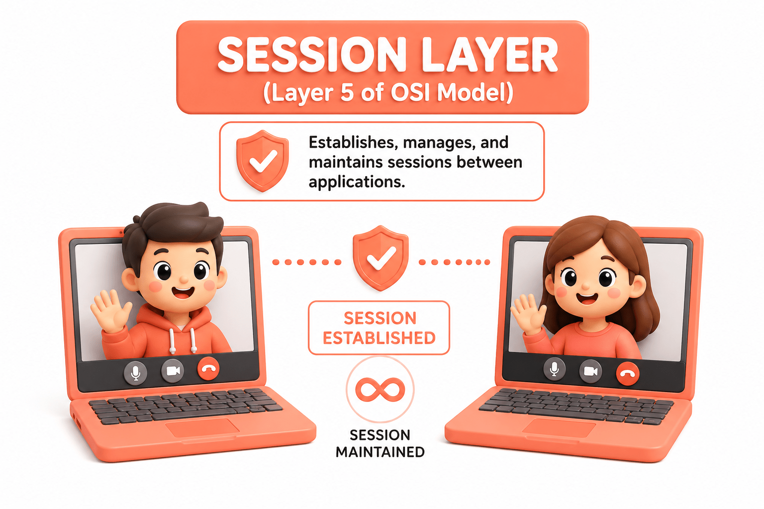
Session Layer (Layer 5):
Handles data encryption, decryption, and formatting. Responsible for data translation, encryption/decryption, and compression to ensure that data is presented in a standard, usable format for the application layer.
Handles encryption & formatting
Example: Converting data into readable format, encrypting passwords

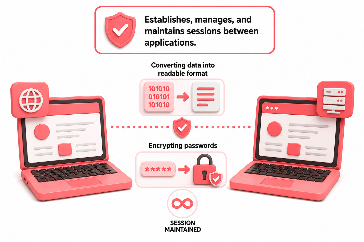
Presentation Layer (Layer 6):
Interfaces directly with user applications (HTTP, FTP, SMTP). Provides network services directly to end-user applications and facilitates communication between software processes over a network.
Closest to the user
Provides services like web, email

Example: Browser, WhatsApp, Gmail
Application Layer (Layer 7):

Browser
Converts web data(HTML,images,videos) into readable format
Encrypts messages and media to keep conversations secure


Gmail
Converts email content into readable text and secures it with encryption

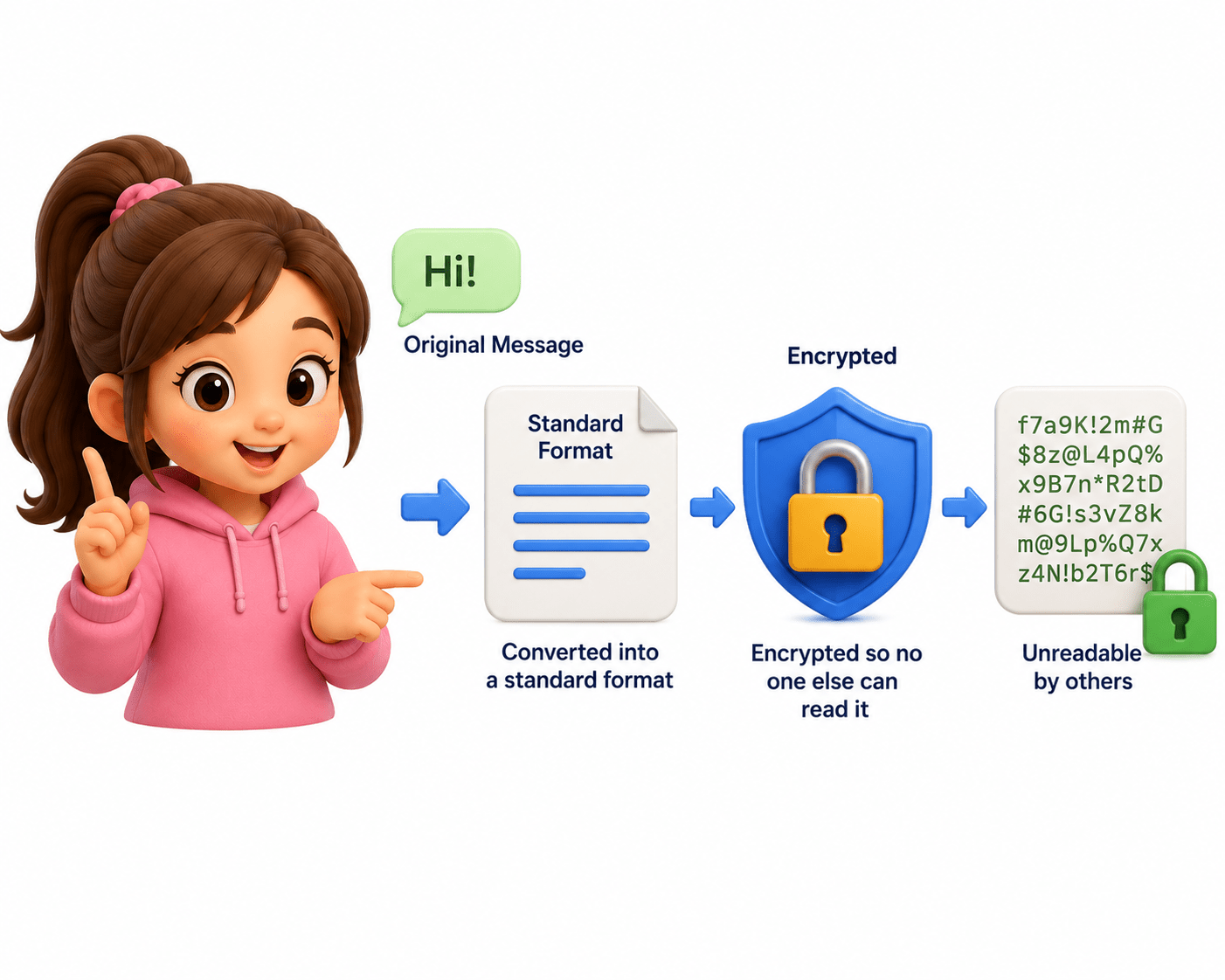
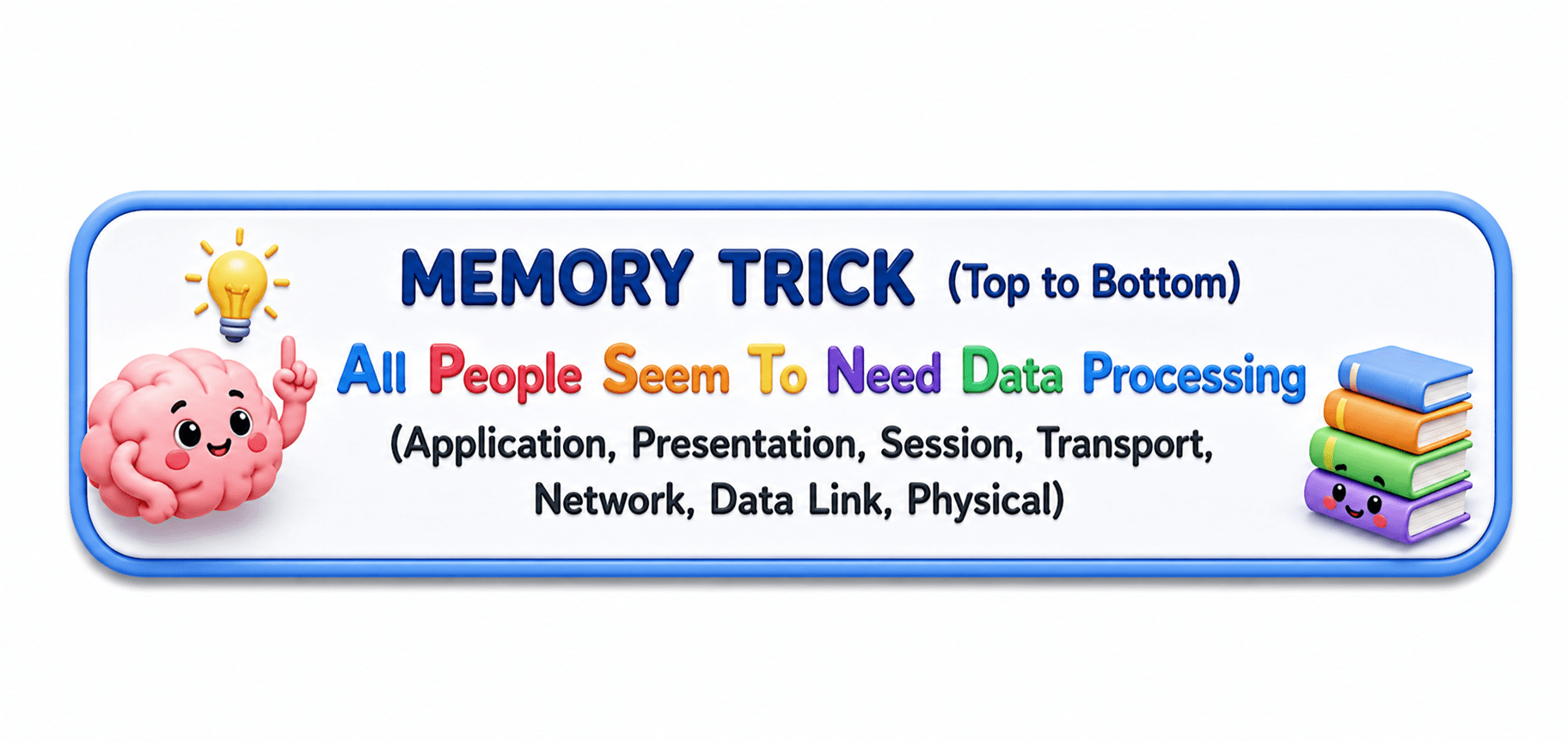
7 - APPLICATION LAYER
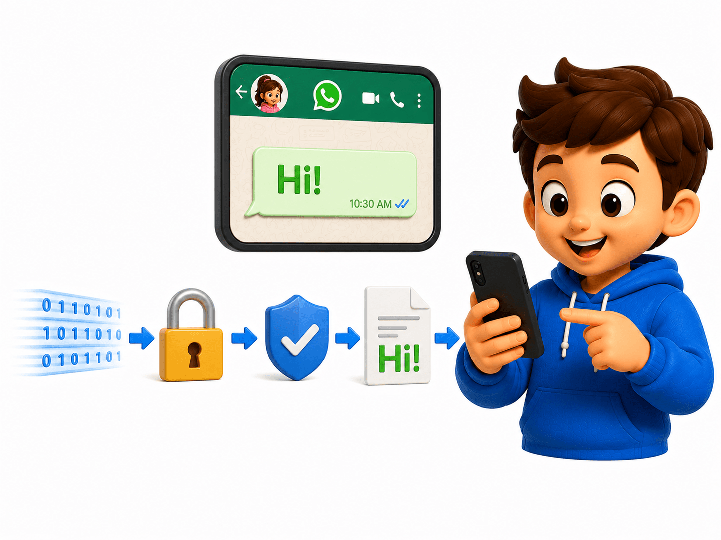
6 - PRESENTATION LAYER
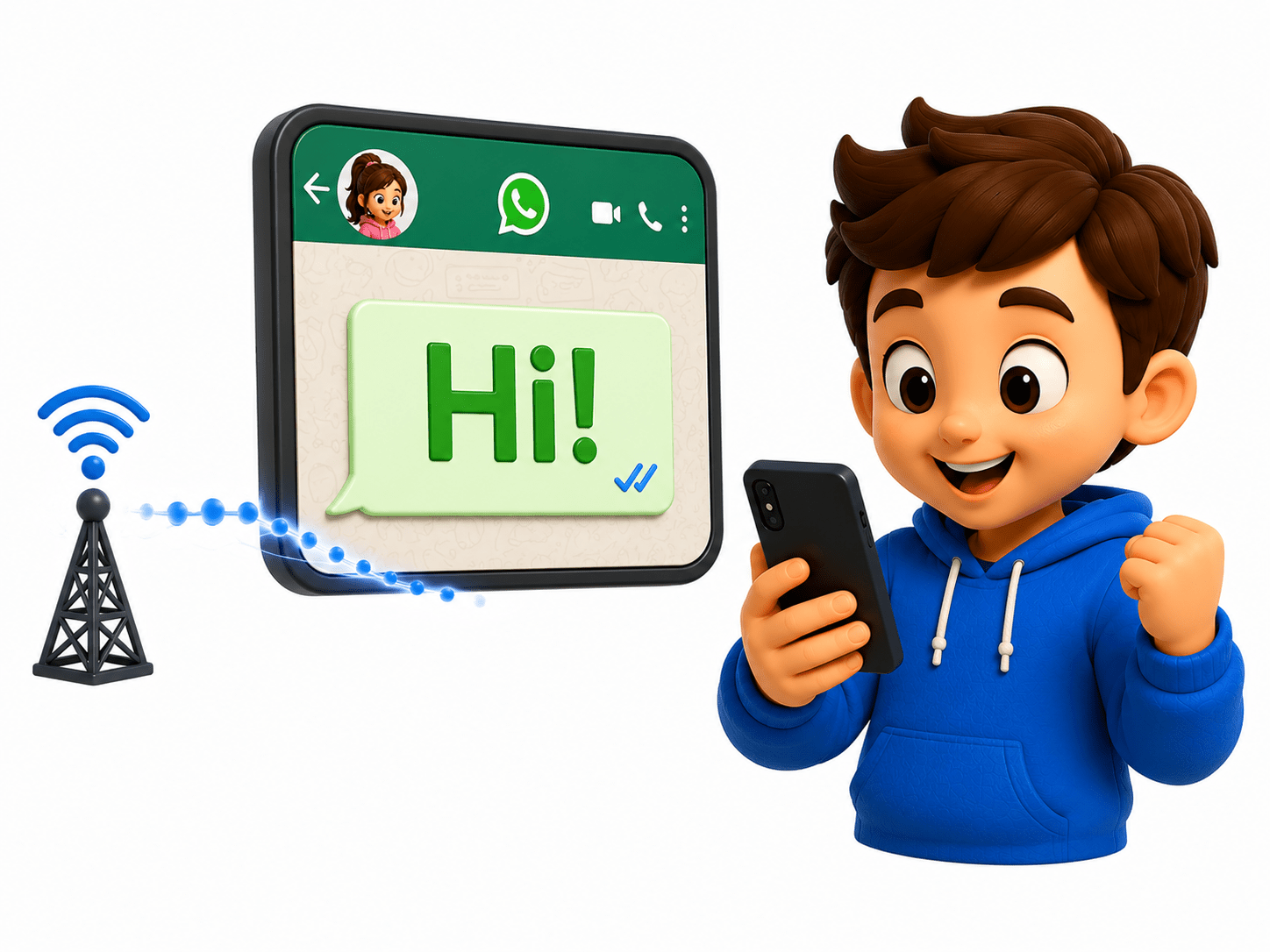
SENDER: Your Phone

- You send a WhatsApp message “Hi!” to your friend.
- Provides network services directly to user applications.
- Converts data into a readable format and handles encryption/decryption.
- Encrypting the message
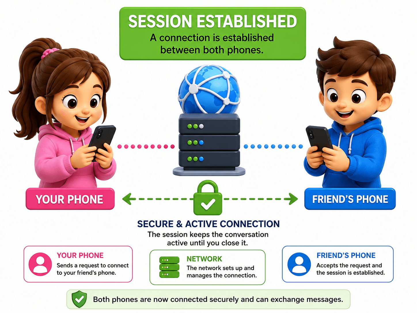
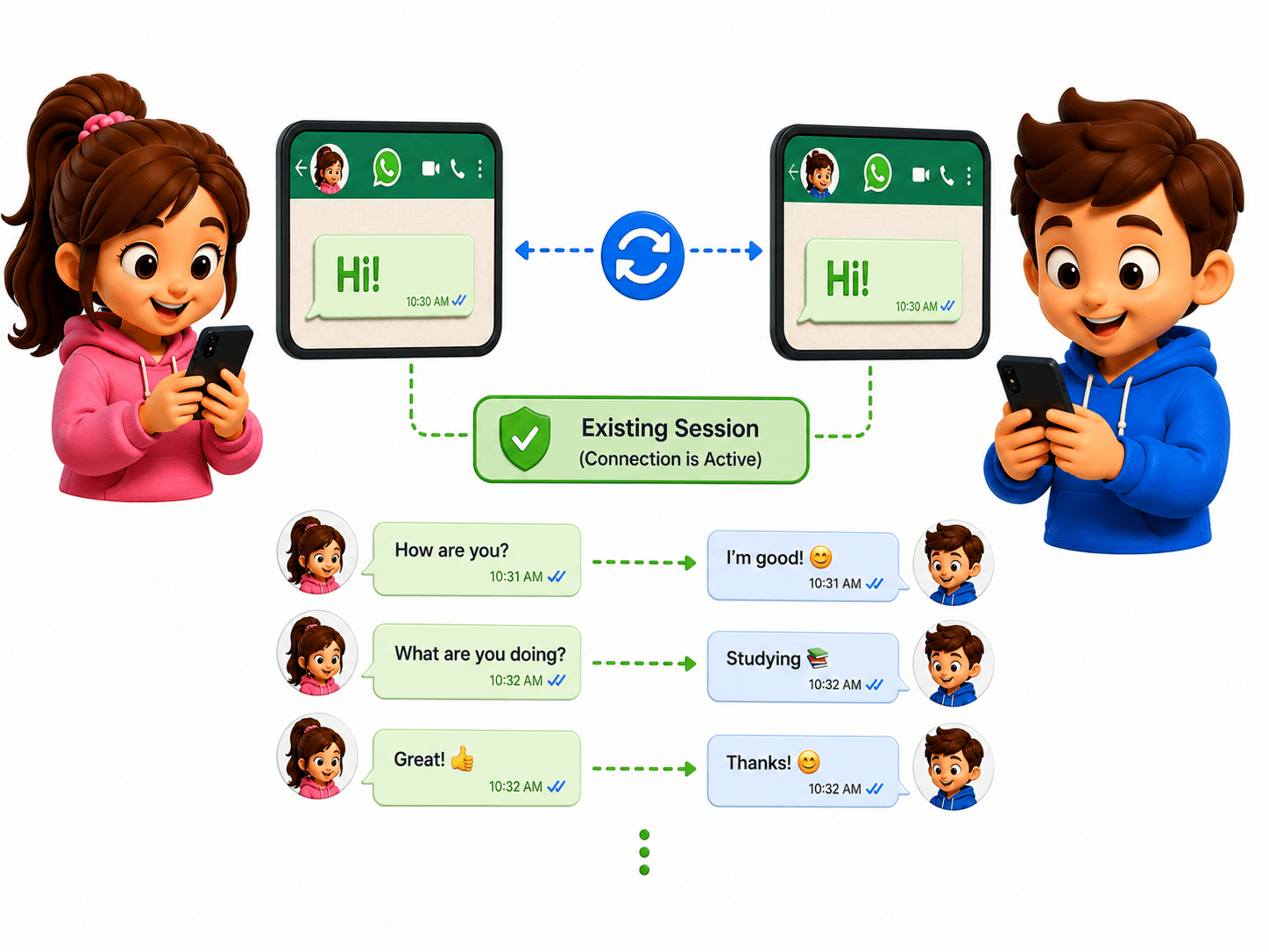
5 - SESSION LAYER
- Creates, manages, and ends communication sessions between devices.
- Keeping chat session active.
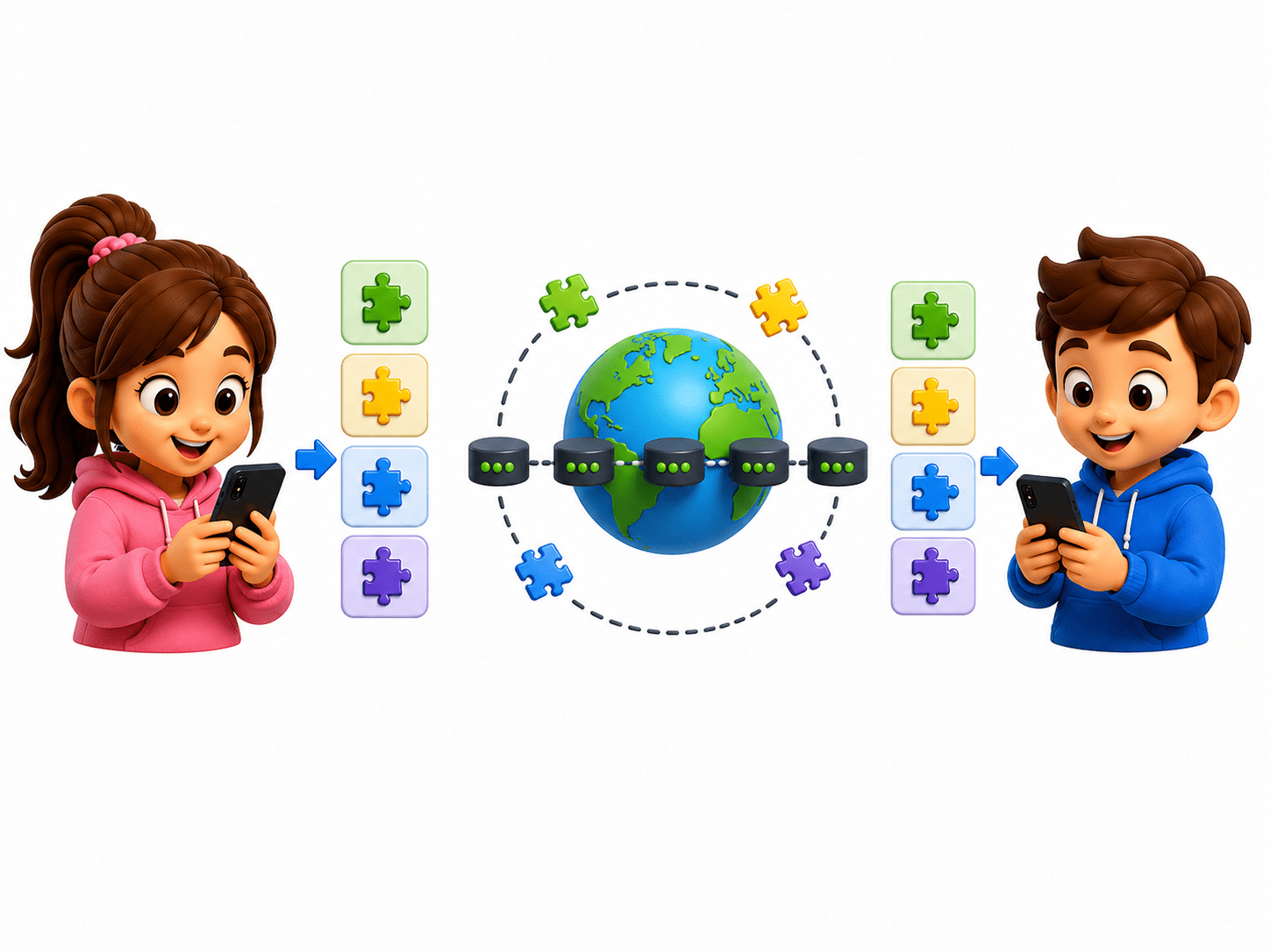
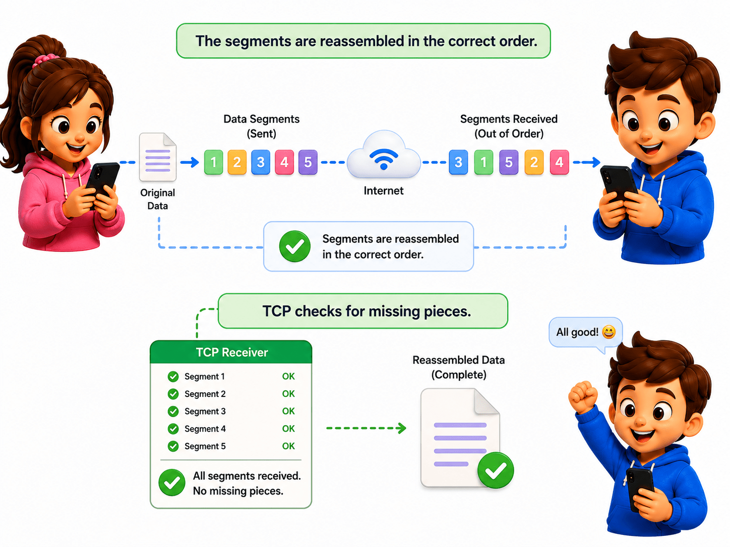
4 - TRANSPORT LAYER
-
Breaks data into smaller segments and ensures reliable delivery.
-
TCP checks if all data reaches correctly.
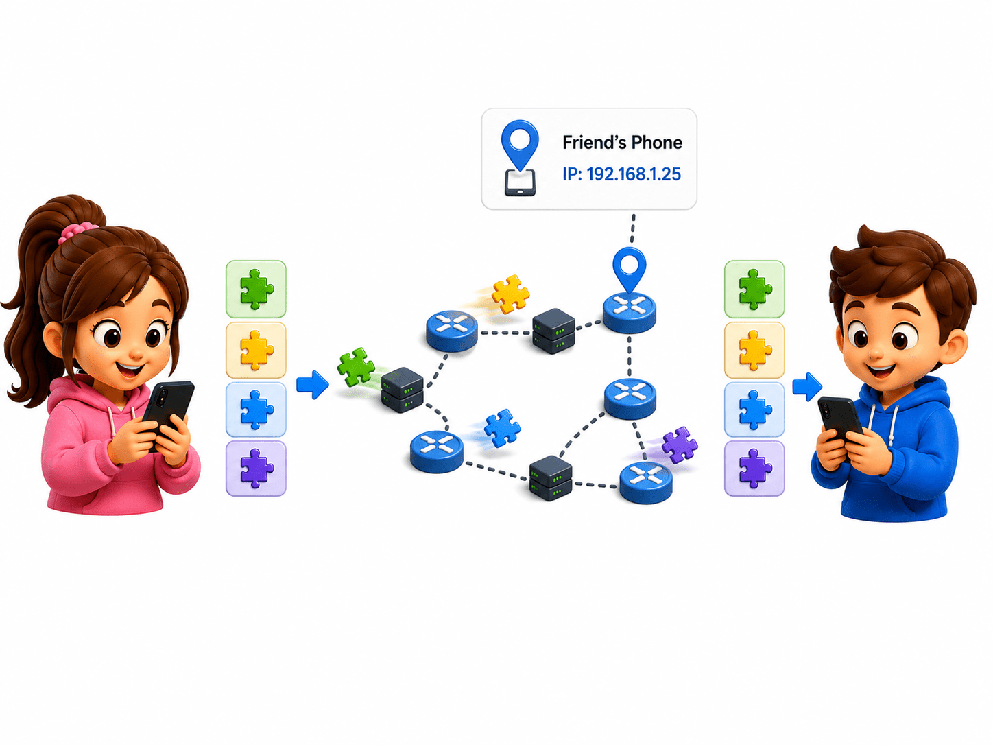
3 - NETWORK LAYER
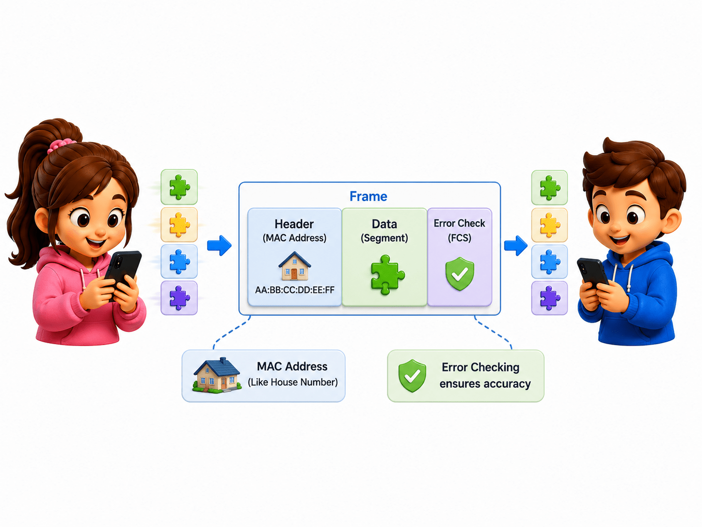
2 - DATA LINK LAYER
-
Adds IP addresses and finds the best route to the destination.
-
Routers forwarding packets across the internet.
-
Adds MAC addresses and creates frames for local network communication.
-
Example: Ethernet and Wi-Fi communication.
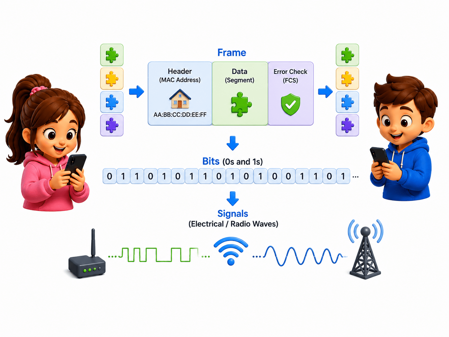
1 - PHYSICAL LAYER
-
Converts data into electrical, optical, or radio signals for transmission.
-
Network cables, switches, radio waves.
RECEIVER: Friend’s Phone
7 - APPLICATION LAYER
6 - PRESENTATION LAYER
-
Delivers the final readable data to the user application.
-
Displaying WhatsApp message.
-
Decrypts and converts data into a usable format.
-
Decrypting whatsapp message
5 - SESSION LAYER
-
Maintains and manages the communication session.
-
Keeping chat sessions active.
4 - TRANSPORT LAYER
-
Reassembles segments and checks for missing or damaged data.
-
TCP ensuring complete file delivery.
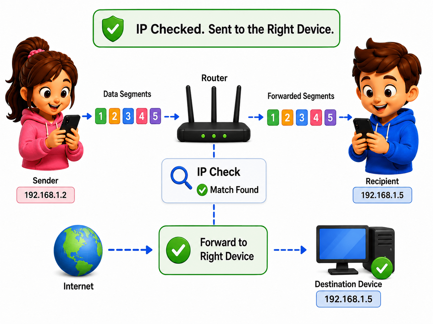
3 - NETWORK LAYER
-
Reads IP addresses and delivers packets to the correct device.
-
Identifying destination IP address.
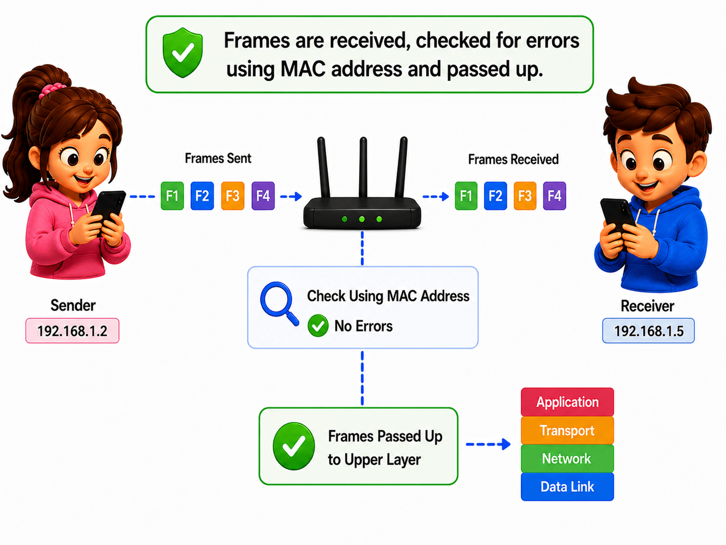
2 - DATA LINK LAYER
-
Checks frames for errors and reads MAC addresses.
-
Verifying data received from the local network.
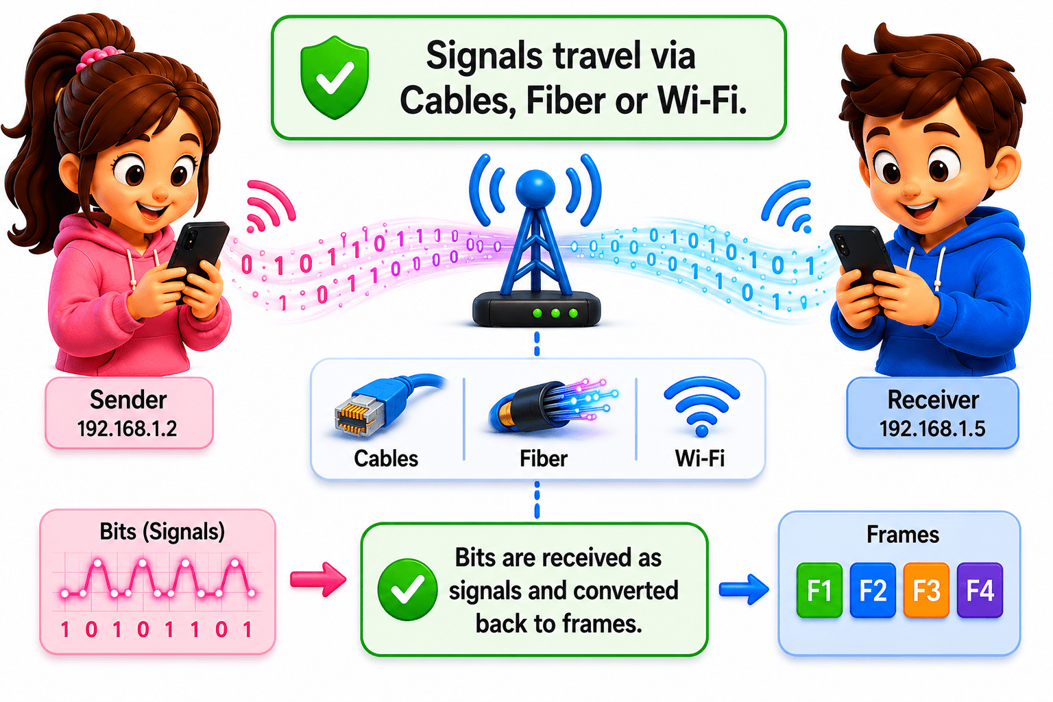
1 - PHYSICAL LAYER
-
Receives raw signals and converts them back into bits (0s and 1s).
-
Receiving signals through cables or Wi-Fi.
Advantages of OSI Model

Simplifies complex network communication
Helps in troubleshooting (identify the layer of Issue easily)
Allows different vendors and technologies to work together.
Each layer can be developed, tested, and updated independently.
Good learning model for students and beginners.
Summary
5
It enables different devices to communicate using common protocols.
4
It helps identify network issues quickly.
3
Each layer has a specific networking function.
2
Layered architecture divides networking into smaller tasks.
1
OSI Model is a 7-layer framework for network communication.
Quiz
Which layer would you investigate if there is NO network signal at all?
A. Network Layer
B. Transport Layer
C. Physical Layer
D. Data Link Layer

Quiz-Answer
C. Physical Layer

Which layer would you investigate if there is NO network signal at all?
A. Network Layer
B. Transport Layer
D. Data Link Layer